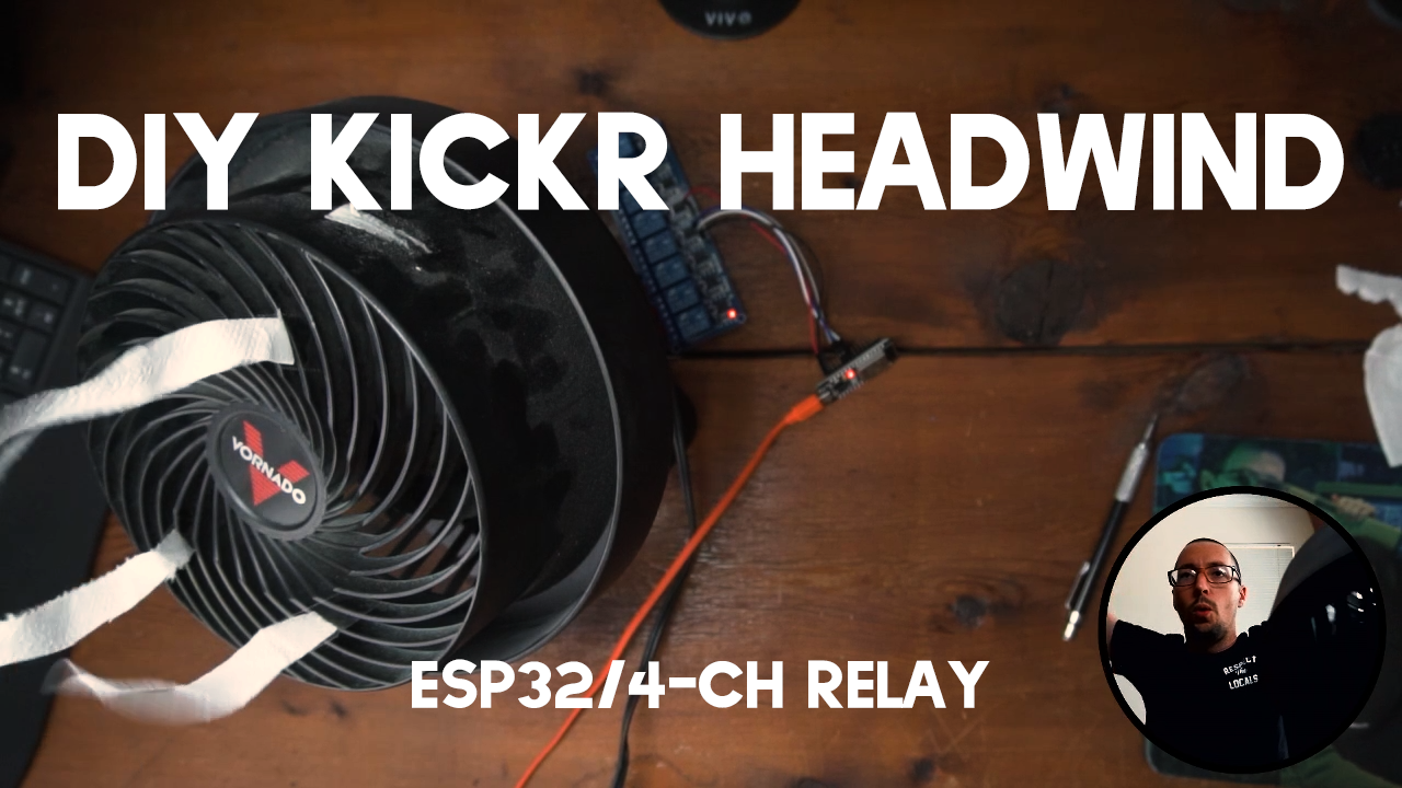
This post will show you how to control your bicycle fan speed with your heart rate monitor.
DIY KICKR Headwind Parts List
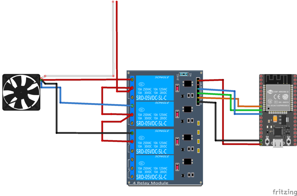
Schematic

DIY KICKR Headwind Code
https://github.com/agrabbs/hrm_fan_control
/**
 * A modified BLE client that will read BLE HRM
 * and control a relay
 * author Andrew Grabbs
 */

#include "BLEDevice.h"
//#include "BLEScan.h"

// Set to true to define Relay as Normally Open (NO)
#define RELAY_NO true

// Set number of relays
#define NUM_RELAYS 3

// Heart Rate Zones
#define ZONE_1 100 // 70 bpm
#define ZONE_2 120 // 100 bpm

// Assign each GPIO to a relay
uint8_t relayGPIOs[NUM_RELAYS] = {25, 26, 27};

// The remote service we wish to connect to.
static BLEUUID serviceUUID("0000180d-0000-1000-8000-00805f9b34fb");
// The characteristic of the remote service we are interested in.
static BLEUUID charUUID(BLEUUID((uint16_t)0x2A37));
//0x2A37

static boolean doConnect = false;
static boolean connected = false;
static boolean notification = false;
static boolean doScan = false;
static BLERemoteCharacteristic* pRemoteCharacteristic;
static BLEAdvertisedDevice* myDevice;

static void notifyCallback(
  BLERemoteCharacteristic* pBLERemoteCharacteristic,
  uint8_t* pData,
  size_t length,
  bool isNotify) {
    Serial.print("Heart Rate: ");
    Serial.print(pData[1], DEC);
    Serial.println("bpm");
    if(pData[1] == 0) {
      for(int i=1; i<=NUM_RELAYS; i++){
        digitalWrite(relayGPIOs[i-1], HIGH);
      }
    }
    else if(pData[1] <= ZONE_1 && pData[1] > 0) {
      Serial.println("ZONE 1!");
      for(int i=1; i<=NUM_RELAYS; i++){
        digitalWrite(relayGPIOs[i-1], HIGH);
      }
      digitalWrite(relayGPIOs[0], LOW);
    }
    else if(pData[1] > ZONE_1 && pData[1] <= ZONE_2) {
      Serial.println("ZONE 2!");
      for(int i=1; i<=NUM_RELAYS; i++){
        digitalWrite(relayGPIOs[i-1], HIGH);
      }
      digitalWrite(relayGPIOs[1], LOW);
    }
    else if(pData[1] > ZONE_2) {
      Serial.println("ZONE 3!");
      for(int i=1; i<=NUM_RELAYS; i++){
        digitalWrite(relayGPIOs[i-1], HIGH);
      }
      digitalWrite(relayGPIOs[2], LOW);
    }
}

class MyClientCallback : public BLEClientCallbacks {
  void onConnect(BLEClient* pclient) {
  }

  void onDisconnect(BLEClient* pclient) {
    connected = false;
    Serial.println("onDisconnect");
  }
};

bool connectToServer() {
    Serial.print("Forming a connection to ");
    Serial.println(myDevice->getAddress().toString().c_str());

    BLEClient*  pClient  = BLEDevice::createClient();
    Serial.println(" - Created client");

    pClient->setClientCallbacks(new MyClientCallback());

    // Connect to the remove BLE Server.
    pClient->connect(myDevice);  // if you pass BLEAdvertisedDevice instead of address, it will be recognized type of peer device address (public or private)
    Serial.println(" - Connected to server");

    // Obtain a reference to the service we are after in the remote BLE server.
    BLERemoteService* pRemoteService = pClient->getService(serviceUUID);
    if (pRemoteService == nullptr) {
      Serial.print("Failed to find our service UUID: ");
      Serial.println(serviceUUID.toString().c_str());
      pClient->disconnect();
      return false;
    }
    Serial.println(" - Found our service");


    // Obtain a reference to the characteristic in the service of the remote BLE server.
    pRemoteCharacteristic = pRemoteService->getCharacteristic(charUUID);
    if (pRemoteCharacteristic == nullptr) {
      Serial.print("Failed to find our characteristic UUID: ");
      Serial.println(charUUID.toString().c_str());
      pClient->disconnect();
      return false;
    }
    Serial.println(" - Found our characteristic");

    // Read the value of the characteristic.
    if(pRemoteCharacteristic->canRead()) {
      std::string value = pRemoteCharacteristic->readValue();
      Serial.print("The characteristic value was: ");
      Serial.println(value.c_str());
    }

    if(pRemoteCharacteristic->canNotify())
      pRemoteCharacteristic->registerForNotify(notifyCallback);

    connected = true;
    return true;
}
/**
 * Scan for BLE servers and find the first one that advertises the service we are looking for.
 */
class MyAdvertisedDeviceCallbacks: public BLEAdvertisedDeviceCallbacks {
 /**
   * Called for each advertising BLE server.
   */
  void onResult(BLEAdvertisedDevice advertisedDevice) {
    Serial.print("BLE Advertised Device found: ");
    Serial.println(advertisedDevice.toString().c_str());

    // We have found a device, let us now see if it contains the service we are looking for.
    if (advertisedDevice.haveServiceUUID() && advertisedDevice.isAdvertisingService(serviceUUID)) {

      BLEDevice::getScan()->stop();
      myDevice = new BLEAdvertisedDevice(advertisedDevice);
      doConnect = true;
      doScan = true;

    } // Found our server
  } // onResult
}; // MyAdvertisedDeviceCallbacks


void setup() {
  Serial.begin(115200);
  Serial.println("Starting Arduino BLE Client application...");
  BLEDevice::init("");
  // Set all relays to off when the program starts - if set to Normally Open (NO), the relay is off when you set the relay to HIGH
  for(int i=1; i<=NUM_RELAYS; i++){
    pinMode(relayGPIOs[i-1], OUTPUT);
    if(RELAY_NO){
      digitalWrite(relayGPIOs[i-1], HIGH);
    }
    else{
      digitalWrite(relayGPIOs[i-1], LOW);
    }
  }

  // Retrieve a Scanner and set the callback we want to use to be informed when we
  // have detected a new device.  Specify that we want active scanning and start the
  // scan to run for 5 seconds.
  BLEScan* pBLEScan = BLEDevice::getScan();
  pBLEScan->setAdvertisedDeviceCallbacks(new MyAdvertisedDeviceCallbacks());
  pBLEScan->setInterval(1349);
  pBLEScan->setWindow(449);
  pBLEScan->setActiveScan(true);
  pBLEScan->start(5, false);
} // End of setup.


// This is the Arduino main loop function.
void loop() {
  // If the flag "doConnect" is true then we have scanned for and found the desired
  // BLE Server with which we wish to connect.  Now we connect to it.  Once we are
  // connected we set the connected flag to be true.
  if (doConnect == true) {
    if (connectToServer()) {
      Serial.println("We are now connected to the BLE Server.");
    } else {
      Serial.println("We have failed to connect to the server; there is nothin more we will do.");
    }
    doConnect = false;
  }

  // If we are connected to a peer BLE Server, update the characteristic each time we are reached
  // with the current time since boot.
  if (connected) {
    if (notification == false) {
        Serial.println("Turning Notification On");
        const uint8_t onPacket[] = {0x01, 0x0};
        pRemoteCharacteristic->getDescriptor(BLEUUID((uint16_t)0x2902))->writeValue((uint8_t*)onPacket, 2, true);
        notification = true;
    }
  }else if(doScan){
    BLEDevice::getScan()->start(0);  // this is just eample to start scan after disconnect, most likely there is better way to do it in arduino
  }

  delay(1000); // Delay a second between loops.
} // End of loop


Thanks so much for producing this, Ive been pressed into building one of these for my brothers swift set-up 🙂
He runs a side by side set-up with his partner and so I was wondering if you knew of a way to tie the MAC address of the HRM within the code to allow them to control only the one fan? I was thinking of something like the ‘static BLEUUID serviceUUID’ but the MAC of the HRM which i could add into the code and input the MAC from either the serial monitor or a bluetooth sniffer.
Thanks again.
Iain, the BLEUUUID should be unique for each HRM, if I am understanding what you’re asking you want two HRM’s to control one fan? This could be possible thru some coding; The highest heart rate would be what controlled the fan. This could be achieved by creating two device models and sampling the two and taking the higher value. I hope this helps!
Awesome writeup and video. Managed to replicate this with my own FAN and it worked ! Am thinking about some modifications (Wifi connected for easier updates/mods and a temperature sensor)
Thanks! Those modifications sound pretty cool, let me know what you settle on.
Pretty cool, I was just thinking about doing something like this.
I think my approach would be to get a 5-6-7-8 speed fan with an IR remote and use an IR blaster or Broadlink device to control it based on speed or heart rate. I’ll definitely use your work as a reference, thanks!
As I am starting o my rocker plate based on your plan, Thought I might find a way to adapt this post (which I am also planning on working through) to some bluetooth controlled LEDs placed between the plates as downlight with colors placed on watts. I’m sure it will be easier to start with heart rate, so that is where I will start, but any thoughts on highjacking power signals from a trainer bluetooth signal to do this?
Ted,
Depends on what trainer you’re using, but you can tap in to the Fitness Machine Service (FTMS) or the Cycling Power Service for the machines that haven’t gotten around to implementing FTMS. Both are both BLE standards. Either of these two will allow you to read the power data, after some decoding. Another thing worth mentioning is that you’ll need to pull power data from a trainer that supports more than one BLE connection, otherwise you’ll tie up your connection.
Good luck and let me know how it turns out!
Thank you for posting this!
I’m not much of a coder, but if I want to use my trainer’s speed (like the Kickr Headwind) to control the fan rather than an HRM, how would I go about doing this?
Eric,
You would need to be able to write code to read your trainers Bluetooth LE FTMS (Fitness Machine Service) or CPS (Cycling Power Service) characteristic to determine the speed. Trainers typically allow multiple connections, so this shouldn’t be a problem with occupying one like it is with the heart rate monitor.
Hope this helps!
Thanks Andrew. Can you help me understand why the values below are set to 0x01 and 0x0 to update the characteristic:
const uint8_t onPacket[] = {0x01, 0x0};
Are these just initial values that get overwritten? And the 0x0 becomes the heart monitor’s BPM once it’s read? Why is the first value set at 0x01?
Hi Andrew,
Hi everyone,
I have seen you project and it looks really great. I have got a Honeywell TurboForce with 3 speed. Do you think this will work with it?
Thanks a lot.
Best regards.
Martin
Should be good!
IIRC connecting 2 or more fan inputs at the same time is bad for the motor. This design depends on software to ensure that only one fan input is connected at a time. However there is a simple wiring change which brings proper isolation to hardware.
Connect line in to Common on relay 1. Leave NC open on relay 1. Connect NO on relay 1 to Common on relay 2.
Connect NC on relay 2 to fan low speed. Connect NO to Common of relay 3.
Connect NC on relay 3 to fan medium speed. Connect NO to fan high speed.
This way relay 1 is on/off, relay 2 is low speed or voltage is passed on to relay 3 which is medium or high speed.
Thanks so much for the tutorial. I bought a Lasco high velocity fan and did this. I also added a 16×2 LCD that displays what zone the fan is in and current heart rate! The only thing that is a little funky is the initial connection. Thanks again.
Hi Andrew,
Thanks for the details. I tried it with Garmin HRM-Pro but had lots of problems because scan can not find the hrm. When i move the esp32 very close to Garmin HRM-Pro, it finally catch it. Connections is disconnected when the distance more than 10/15 cm. I have searched and found some informations about power level. I changed the power level to ESP_PWR_LVL_P9 but it doesn’t solve the issue. Do you have any suggestion ?
Hi guys. Hi guys. I have a problem. I have no idea about programming, but I modified the script a bit. I have set up 3 zones:
// Heart Rate Zones
#define ZONE_1 110 // 100 bpm
#define ZONE_2 120 // 110 bpm
#define ZONE_3 190 // 120 bpm
Additionally, I would like the fan to turn on not when the HRM is connected, but when the heart rate exceeds 99 BPM.
static void notifyCallback(
BLERemoteCharacteristic* pBLERemoteCharacteristic,
uint8_t* pData,
size_t length,
bool isNotify) {
Serial.print(“Heart Rate: “);
Serial.print(pData[1], DEC);
Serial.println(“bpm”);
if(pData[1] == 99) {
for(int i=1; i<=NUM_RELAYS; i++){
digitalWrite(relayGPIOs[i-1], HIGH);
Unfortunately, this is where the problem . Sometimes HR drops beyond the value of 99BPM, e.g. the next value is 98 or 97 and then the fan does not turn off. What do I need to change. Thank you in advance for your help.
Dario,
It looks like you are doing `if(pData[1] == 99) {` That line states if the data is 99. So your code suggest that only if the data is 99 do you set all relays HIGH. I would do something along the lines of `if pdata >= 99 { set to high if not already on high }`. Hope that helps!
Thank you. Works great. Regards
I have one more question. ESP32 wroom has a built-in LED (LED2) – I think so. Can you modify the code so that LED2 turns on after BLE connection is established with HRM? Sometimes the script does not run automatically and it has to be run manually on the disc. This is problematic when riding a trainer. If it worked, you could look at the board to see if it had established a connection with HRM. Thank you in advance for any help. Regards.